Plant settings
These settings are available in the following locations:
Plant Preferences dialog box (creating an object)
Plant Settings dialog box (editing an object)
Object Info palette (editing an object)
Edit Plant Style dialog box (creating or editing a style)
Plant Style Manager (editing a style)
The only fields required for a plant style to function are the unique Style Name and Plant/Tag ID, and the Spread, and Height; specify as few or many of the settings available in these dialog boxes as needed for the plant style to serve its purpose. Every plant instance in the drawing is based on a plant style. You can create plant styles with a combination of parameters that are determined by style or by instance. Style parameters have a fixed value established by the style; instance parameters can be set independently for each instance of the object in the drawing; see Concept: Plug-in object styles and Creating plug-in object styles. To edit parameters locked by style, or to change parameters from by style to by instance, you must edit the style, as described in Editing plant styles; editing a plant style changes all plants that use that style.
When editing an instance in the drawing, either directly in the Object Info palette or in the Settings dialog box, only parameters set by instance can be edited. Some parameters specific to the placement of an instance are available only on the Object Info palette, not in a dialog box; those parameters are listed at the bottom of the page. Values and settings entered on the Edit Plant Style or Plant Preferences dialog boxes or the Plant Style Manager become the default for plants placed in the future; values changed in the Plant Settings dialog box or Object Info palette apply only to the selected plant.
The organization and parameters in the Plant Preferences, Plant Settings, and Edit Plant Style dialog boxes are identical, except for the controls related to selecting or creating a style. Each dialog box is divided into panes with groups of related parameters in each. The main settings required for a plant are found on the first three panes. Additional settings for more advanced users are found on panes in the Extended Settings section. Plant Styles can also be edited from the Plant Style Manager; see Plant Style Manager.
Plant settings: Overall
Click to show/hide the parameters.Click to show/hide the parameters.
|
Parameter |
Description |
|
Use Style (Plant Preferences and Plant Settings dialog boxes) |
Select a style from the Resource Selector |
|
Duplicate Style (Plant Preferences and Plant Settings dialog boxes) |
Opens the Edit Plant Style dialog box to create a duplicate plant style based on the selected plant's style |
|
Plant Style Name (Edit Plant Style dialog box) |
Displays the plant style's name as specified in the Name Formula; this name also displays in the Resource Manager and Object Info palette |
|
Name Formula (Edit Plant Style dialog box) |
Enter a name for the plant style and select a prefix and suffix to be appended to the name, if desired. You may find it effective to enter the Latin (botanical) name in the prefix field, and reserve the main name field for more specific information that helps distinguish among plants with the same botanical name. The Plant Style Manager, which allows you to edit multiple plant styles at once, has some additional controls. When multiple plant styles are selected, Specify Plant Style Name displays <Different>, and the Main Name Field appears empty. Load Main Name from is set to Current by default, to preserve the current main name value for each of the selected plant styles. Alternatively, select to automatically populate the Main Name Field with the plant's Latin name, common name, or plant tag ID, or select None to clear the field for all selected plant styles. |
|
Previews |
Dynamically previews the plant appearance, showing how it will appear when added to the drawing |
|
Top/Plan Preview |
Displays the 2D component of the plant symbol |
|
3D Preview |
Displays the 3D component of the plant symbol, if one has been added to the symbol definition |
Plant settings: Species and Data pane
Click to show/hide the parameters.Click to show/hide the parameters.
|
Parameter |
Description |
|
Species |
|
|
Latin Name |
Specifies the plant genus and species (botanical name) |
|
Common Name |
Specifies the plant common name or names |
|
Copy External Data (Edit Plant Style dialog box) |
Opens the Copy External Data web palette so you can import plant data from nurseries that partner with Vectorworks; see Copying external plant data |
|
Plant Catalog (Edit Plant Style dialog box) |
This workflow is no longer needed to manage, place or generate reports from plant styles; plant styles now contain all needed data. However, if you opt to use plant catalogs or the plant database: Depending on the selection made in the Choose Plant Data Source dialog box (see Selecting the plant data source (legacy)), plant data can be either associated with plants from plant catalogs or from the plant database. If plant catalogs are the source, the Select Plant Data dialog box opens. Select the plant to associate from the list. The plant data from the catalog is imported. See Using plant catalogs (legacy) for additional information. If the plant database is the source, the plant database opens, if it is not already open (this may take several seconds). A dialog box in Vectorworks indicates that Vectorworks is waiting for you to select data from the plant database for the plant style. If you change your mind about obtaining the plant style data from the plant database, click Cancel Data Acquisition. Select a plant record from the plant database as described in Searching for plants. Once the correct plant has been located, from the plant database, select Vectorworks > Use Currently Selected Record. This associates the plant database record with the plant style. From either source, once the plant data has been associated with the plant style, the catalog or database information updates the appropriate plant style parameters, if specified when the plant data source was selected. |
|
Data |
|
|
Category |
Select the plant's category. To edit the list of available values, or to import a list or export the current list as an .xml file, select Manage Categories. |
|
Plant/Tag ID |
Identifies the plant with a unique code often used for the plant abbreviation. This code appears in the plant list and on ID tags, if selected (see Plant ID codes for the definition of common code categories) |
|
Scheduled Size |
Size information for the plant. This can, for example, be the caliper or girth for a tree, form, or container size. All specification data for the plant can be recorded here, or it can be separated into individual parameters in the More Data pane. This data displays in the Plant List worksheet. |
|
Quantity Type |
Determines the Quantity value for the attached Plant record, primarily for the purpose of calculating plant worksheets with the plant cost per count or the cost per area. The Quantity Type can be defined by unit count, dripline area, or border area: Count: Counts the number of plants within an array of plants Dripline area: Considers the area, in current document units, of the drip line polygon (the tight bounding polygon around the plants) Boundary area: Considers the area, in current document units, of the plant array polygon as drawn |
|
Price Code (SKU) |
Specifies the price code entry in Stock Keeping Units (SKU) |
|
Price |
Indicate the plant cost per unit of quantity; the plant cost and quantity are reflected in the Extended Price calculation in the Plant List worksheet |
|
Planting Schedule Comments/Nursery Schedule Comments |
Specifies default comments about the plant that display in the Plant List worksheet |
Plant settings: Size and Spacing pane
Click to show/hide the parameters.Click to show/hide the parameters.
|
Parameter |
Description |
|
Size |
|
|
Spread |
Specifies the default plant spread diameter for both single and multiple plant placement. This value can be used for install or mature size, or for an expected size at a specific age. |
|
Height |
Sets the default height of the plant. This value can be used for install or mature size, or for an expected size at a specific age. |
|
Hedge |
|
|
Use hedge mode |
Allows use of Hedge mode when placing plants with this style; some space and array options are not available with hedge mode |
|
Hedge Mode |
Select the arrangement of hedge rows when Hedge mode is enabled. Rectangular: Places as many single rows of plants as indicated in the Hedge Rows field; for multiple rows, select Offset rows to give them a staggered appearance. If you use this mode, specification in plants per linear unit is counted for each row individually. Staggered Row: Places a single row of plants, but the row is staggered so it appears like two rows. Triple Staggered Row: Places a single row of plants, but the row is staggered so it appears like three rows. |
|
Hedge Rows |
For Rectangular Hedge Mode, specifies the number of hedge rows to create when Hedge mode is enabled; if there are multiple rows, select whether to offset the rows |
|
Hedge Row Spacing |
For Rectangular Hedge Mode, select whether the row spacing is the same as the plant spacing or a different fixed value, and enter the value |
|
Space and Array Modes Options |
|
|
Spacing by |
For the Poly-Vertex Placement, Poly-Edge Spaced, Rectangular Array, and Triangular Array insertion modes, sets the default spacing between plants at insertion; select Distance, Rate, or Coverage |
|
Distance |
Sets the horizontal distance between plants (Plant Spacing) and between vertical rows of plant arrays (Array Row Spacing). Same as Plant Spread: Sets the Plant Spacing to be the same as the Spread setting Fixed Spacing: Places plants at the specified distance Best Fit: Places a plant at the start and end of each path segment and then distributes the plants evenly as close as possible to the specified distance. This allows you to always have a plant at each path vertex. Count: Distributes the specified number of plants evenly along the each line segment or within the array Same as Plant Spacing: Sets the Array Row Spacing to be the same as the Plant Spacing selection |
|
Rate (rectangular and triangular array or hedge) |
Calculates the plant spacing based on the plant area or length. Specify the rate: Plants per square unit: For arrays, spaces the plants according to the set density, with the square unit specified in the document settings Unit on center: For arrays, spaces the plants from center to center, according to the length units specified in the document settings Plants/Linear Unit: For hedges, spaces the plants according to the set rate, with the unit specified in the document settings Plants/Linear Unit, Best Fit: Places a plant at the start and end of each path segment and then distributes the plants evenly as close as possible to the specified distance. This allows you to always have a plant at each path vertex. |
|
Coverage |
Calculates the plant spacing based on the actual plant area and Spread values, and places them according to the set Percentage. A value of 100%, for example, indicates full coverage, with plants spaced according to the Spread. |
Plant settings: Insertion Options pane
Click to show/hide the parameters.Click to show/hide the parameters.
|
Parameter |
Description |
|
Mode (Plant Preferences and Plant Settings dialog boxes only) |
Select the default placement mode for this plant |
|
Offset from Path |
To offset the plants from the drawn path, enter the offset distance. A positive number offsets the plants to the right of the drawn line, a negative number to the left. Hedges with multiple rows always add the additional rows to the left of the drawn line, which may affect the offset calculation. |
|
Include on plant list |
Includes this plant on a plant list |
Plant settings: Graphics pane
The plant graphics, which are defined by the plant style, can easily be created from a 3D symbol, from automatically generated 3D geometry, from a Maxon Plant's 3D graphics, from an existing plant, or from an image.
Plant graphics can also be created from 2D and optionally 3D drawing objects, plant images and image props. Once the plant has been created, edit the symbol components as necessary; see Editing symbol definitions.
Click to show/hide the parameters.Click to show/hide the parameters.
|
Parameter |
Description |
|
Edit Current Graphics |
Closes the Edit Plant Style dialog box to set all parameters, and opens object editing mode to edit the 2D or 3D graphics for the plant symbol; see Object editing mode. Alternatively, right-click on a plant instance that uses the style, and select Edit from the context menu, and then click 2D Graphics or 3D Graphics. Editing the plant attributes from an instance edits the plant style and affects all plants that use that style. |
|
Replace Current Graphics |
Opens the Replace Top/Plan Graphics or Replace 3D Graphics dialog box so you can specify the replacement graphic; see Replacing plant style graphics. Replacing graphics does not affect the plant style's spread or height, so in the Plant Style Manager, you can select multiple plant styles and batch replace their geometry. |
Plant settings: Appearance pane
A document preference makes it easy to give plans a uniform appearance by applying a document-wide shadow style to all plants and massing models in a drawing (see Document preferences: Plan Shadows tab), but this document preference can be overridden for plant instances or plant styles. The outline, massing, and shadow parameters can be toggled on or off for all plants in a document by selecting View > Show > Show or Hide Plant Details.
The massing, outline, tick marks, and shadow effects display in Top/Plan view only; plant shadows and tick marks do not display in worksheet images or graphic legends.
Click to show/hide the parameters.Click to show/hide the parameters.
|
Parameter |
Description |
|
Plan View Effects |
|
|
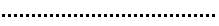
Polyline Display |
For multiple plant placements, changes the display of the boundary or center polyline defining the plant cluster shape.
|
|
Class |
To control the polyline's appearance and visibility, select a class from the list of classes present in the drawing, or create a new class. Select <Plant Class> to place the polyline in the same class as the plant object. |
|
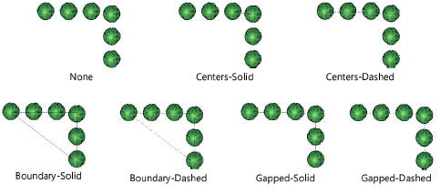
Mass Outline |
Select a plant outline style.
The outline’s pen attributes can be changed for selected plant objects in the Attributes palette. |
|
Class |
To control the outline's appearance and visibility, select a class from the list of classes present in the drawing, or create a new class. Select <Plant Class> to place the outline in the same class as the plant object. The Attributes palette only affects the mass outline if it is assigned to the plant class. |
|
Apply fill across plant grouping |
A continuous outline is created around overlapping plants, and internal details are hidden. The 2D appearance of the massed group is controlled by the back polygon in the plant symbol group, so massing could cause the plant to display without a fill color. (An alternative way of hiding plant details is to use the Plant-Components classes to control the visibility of elements within the plant symbol.)
Keep in mind the following points about this setting: Open areas in a plant style's background fill cannot be filled. Plants that contain bitmap images cannot be massed. Hedges only fill when inserted with Poly-Edge Spaced mode. If a fill is not applied to a hedge or row of plants, it might indicate the plants are slightly separated; only plants that touch each other are filled as a group. Spacing that is set to a best fit option may create a small gap. |
|
Show shadow |
Displays shadow effects in Top/Plan view only. Select whether to use the plan shadows settings in document preferences or custom shadow settings, and click the appropriate button to confirm or adjust the settings; see Document preferences: Plan Shadows tab or Plant shadow settings. |
|
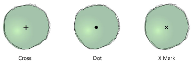
Tick Mark |
|
|
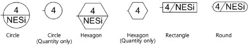
Style |
Select a tick mark (plant center mark) style
|
|
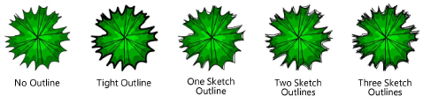
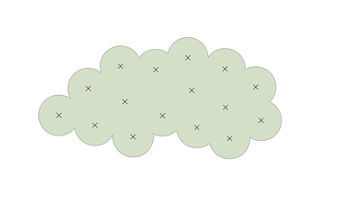
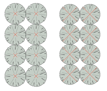
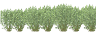
Size |
Specifies the tick mark size in document units. The display is page based, so a tick appears larger at a smaller scale.
The same plants and the same tick mark style and size, shown at two different scales |
|
Class |
To control appearance and visibility, select a class for the tick mark from the list of classes present in the drawing, or create a new class. Select <Plant Class> to place the tick mark in the same class as the plant object. |
|
Rotation and Variation |
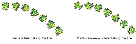
These settings don't affect the plant's specified spread and height, only the appearance in a drawing. The rotation and variation options are especially effective for plants that are not round, such as espaliered trees or climbers along a wall. |
|
Plant Rotation |
For multi-plant placements, orients the plants in the horizontal direction, rotates the plants along the line created by the drawn polygon, or rotates the plants randomly, creating a more natural appearance |
|
Plant Diameter Variation |
Keeps the plants at a fixed size, or randomly varies the plant diameter according to the specified percentage of variation
|
|
Plant Height Variation |
Keeps the plants at a fixed height, or randomly varies the plant heights according to the specified percentage of variation
|
Plant settings: Root Zones pane
Click to show/hide the parameters.Click to show/hide the parameters.
|
Parameter |
Description |
|
Root Ball |
The root ball is the main mass of the plant's roots |
|
Show |
Select which view displays the root ball: 2D Only 3D Only 2D and 3D To hide the root ball, select Bare Root (None). |
|
Shape |
Select the 3D shape of the root ball |
|
Size |
Select the size of the root ball. The values available depend on the selected Shape. To add, edit, or delete custom sizes, see Adding, editing, or deleting custom root ball sizes. |
|
Class |
To control appearance and visibility, select a class from the list of classes present in the drawing, or create a new class. Select <Plant Class> to place the root ball in the same class as the plant object. |
|
Attributes by class |
Select to set all 2D root ball attributes by class. If this parameter is selected, Line Style and Line Color are disabled. |
|
Line Style |
Select the line style of the root ball |
|
Line Color |
Select the line color of the root ball |
|
Planting Excavation |
The planting excavation is the area that needs to be dug out for the root ball to be planted |
|
Show |
Select which view displays the planting excavation: 2D Only 3D Only 2D and 3D To hide the planting excavation, select None. |
|
Shape |
Select the 3D shape of the planting excavation |
|
Depth |
Select the planting excavation depth. To specify a custom depth, select Custom and specify a Value. |
|
Value |
Displays the value of the planting excavation Depth |
|
Diameter (Round) |
Select the planting excavation diameter. To specify a custom diameter, select Custom and specify a Value. The diameter must be large enough to fit the root ball shape. |
|
Side (Rectangular) |
Specify the side dimension of the rectangular Shape. To add, edit, or delete custom sizes, and to specify non-vertical sides and excavation components, see Adding, editing, or deleting custom rectangular plant excavation sides. |
|
Value |
Displays the value of the planting excavation Diameter and/or Side |
|
Class |
To control appearance and visibility, select a class from the list of classes present in the drawing, or create a new class. Select <Plant Class> to place the excavation in the same class as the plant object. |
|
Attributes by class |
Select to set all 2D planting excavation attributes by class. If this parameter is selected, Line Style and Line Color are disabled. |
|
Line Style |
Select the line style of the planting excavation |
|
Line Color |
Select the line color of the planting excavation |
Adding, editing, or deleting custom root ball sizes
To add, edit, or delete root ball sizes:
On the Root Ball tab, select a root ball Shape. The selected shape determines the values available in the Size list.
The Container and the Balled and Burlapped Shape allow a flanged root ball, with different diameters at the top and bottom of the shape.
Select Edit Custom Items from the Size list.
The Edit Custom Items dialog box opens.
Do one of the following:
To add an item, click Add; the Add Custom Dimensions dialog box opens. Specify the Name and dimensions. The calculated Volume displays. Click OK; the item is added to the Edit Custom Items dialog box.
To edit an item, select the item and click Edit; the Edit Custom Dimensions dialog box opens. Edit the Name and/or one or more dimensions. The calculated Volume displays. Click OK; the edited item is displayed in the Edit Custom Items dialog box.
To delete an item, select the item and click Delete.
Click OK.
If you added or edited an item, the item is displayed in the Size list. If you deleted an item, the item is removed from the Size list.
Adding, editing, or deleting custom rectangular plant excavation sides
Rectangular excavations allow a flanged excavation, with different diameters at the top and bottom of the shape. You can also specify backfill components for a rectangular excavation pit.
To add, edit, or delete excavation side sizes:
On the Plant Excavation tab, select a rectangular excavation Shape.
Specify the Depth.
Select Edit Custom Items for the Side dimension.
The Edit Custom Items dialog box opens.
Do one of the following:
To add an item, click Add; the Add Custom Dimensions dialog box opens. Specify the Name. Enter two of the dimensions to automatically calculate the third dimension (with the calculator next to its button); the dynamic preview shows the dimensions that need to be entered. The calculated Volume displays. Click OK; the item is added to the Edit Custom Items dialog box.
To edit an item, select the item and click Edit; the Edit Custom Dimensions dialog box opens. Edit the Name and/or one or more dimensions. The calculated Volume displays. Click OK; the edited item is displayed in the Edit Custom Items dialog box.
To delete an item, select the item and click Delete.
While adding or editing a custom dimension, specify the backfill components for the excavation by clicking Edit Components.
The Planting Excavation Backfill Components dialog box opens.
Click to show/hide the parameters.Click to show/hide the parameters.
|
Parameter |
Description |
|
Preview |
Displays a sectioned preview of the backfill structure, including any defined components. The top of the preview backfill indicates the top part of the slab as it will be drawn. |
|
Overall Thickness |
Displays the thickness of the backfill, which is determined by the thickness of its components. Backfill always has one component by default, set to the excavation Depth. |
|
Backfill component list |
Lists the backfill components in order from top to bottom; click on a Name, Description, or Thickness to edit it. The total thickness of the components should be equal to the Depth. |
|
New |
Adds a component to the list |
|
Duplicate |
Duplicates one or more selected components; the duplicates are added to the component list right below the originally selected components |
|
Delete |
Deletes one or more selected components |
Click OK twice.
If you added or edited an item, the item is displayed in the Size list. If you deleted an item, the item is removed from the Size list.
Plant settings: Tag pane
The Data Tag tool provides more flexible options for tagging plants; see Adding data tags and labels.
To create a custom plant tag using the plant object's tag capabilities, see Creating a custom plant tag. After creation, the plant tag’s appearance can also be modified via the Object Info palette, tag class settings, and the control point locations on the drawing (see Plant tag appearance).
Click to show/hide the parameters.Click to show/hide the parameters.
|
Parameter |
Description |
|
Display |
Select whether to display a plant tag to the right or left of the leader line, in the center of the plant or group of plants, or to display no tag. A Center tag has no shoulder or leader; set the X/Y Offset for Center tags, if needed. |
|
Class |
To control appearance and visibility, select a class from the list of classes present in the drawing, or create a new class |
|
Approach Angle |
Specifies the angle of the leader line, from 0 to 360°. Setting the same angle for several selected plants aligns their leader lines, for an attractive planting plan (see Aligning and distributing leader lines). |
|
Shoulder Angle |
When a tag shoulder line is enabled, sets the angle of the shoulder line and, if selected, tag display, from 0 to 360°. To display the plant tag to the left, specify an angle greater than 90 or less than 270 degrees. To display the plant tag to the right, specify an angle less than 90 or greater than 270 degrees. Setting the same angle for several selected plants aligns their shoulder lines, for an attractive planting plan. |
|
Bubble |
Specifies the bubble style, if any, for displaying quantity or optionally, Plant ID, with the plant tag
|
|
Top/Center/Bottom |
The custom tags present in the drawing and the predefined plant record field combinations for tags are listed. Specify the information to display on each level of the plant tag. For the center level, select Continuation Line to continue the shoulder as a dividing line between the top and bottom tag information. Alternatively, select Set Custom Tag to define a custom plant tag (see Creating a custom plant tag). |
|
Enable tag shoulder line |
Adds a shoulder line to the leader line; adjust the shoulder angle with the shoulder control point, or by entering a tag Shoulder Angle |
|
Snap tag to plant centers |
Snaps the end of the leader line to the center of the plant; deselect to adjust the endpoint location manually |
|
Display tag line marker |
Displays a marker at the end of the leader line; specify the marker to use by editing the plant tag class (see Setting class properties) |
|
Image Size |
Sets the size of any images included in a custom plant tag |
Plant settings: Sustainability pane
The sustainability pane allows you to attach one or more sustainability frameworks to the object. You can attach and specify frameworks and then save the object as a styled object, saving time. Each object's specific parameters can be edited later from the Data pane of the Object Info palette.
Considerations apply when calculating the Biodiversity Net Gain (BNG) metric. Only individual, free-standing trees are included in calculations. For hedgerows with trees, or for woodland habitats, the trees are included in the overall habitat and they are not reported individually.
For the Biomass metric, the drip area of the plant is used as the tree area; overlapping plants are not an issue.
For more information on sustainability frameworks and associated parameters, see The Sustainability Dashboard.
To attach and specify a sustainability framework:
Click <New Framework> to select a framework to attach from the Selected Framework list.
Click Edit Framework to specify the sustainability parameters for that framework.
The available options depend on the selected framework. The options that are not part of the Sustainability Dashboard are described in the table below.
The framework's parameters affect the associated sustainability framework calculations, if applicable, as objects are placed in the drawing. View the results in the Sustainability Dashboard.
Click to show/hide the parameters.Click to show/hide the parameters.
|
Parameter |
Description |
|
Frameworks list |
Lists the frameworks attached to the object. Click <New Framework> to attach a framework. |
|
Selected Framework |
|
|
Framework |
Lists the available frameworks and metrics. Many of these frameworks are associated with metrics on the Sustainability Dashboard; the others are described below. |
|
Edit Framework |
Opens an editing dialog box to specify sustainability parameters for the object |
|
Delete Framework |
Deletes the selected framework from the object |
|
Frameworks not currently part of the Sustainability Dashboard |
|
|
Permeable Surface |
|
|
Permeable Surface |
Select whether the object is permeable or non-permeable. If it is permeable, enter the Rate, and select the units. |
|
Runoff Coeff |
Enter the runoff coefficient |
|
Solar Reflectance Index (SRI) |
Enter the solar reflectance index value |
Plant settings: Maintenance pane
The Maintenance pane indicates maintenance and propagation requirements for the plant, including its fire resilience and irrigation requirements.
Click to show/hide the parameters.Click to show/hide the parameters.
|
Parameter |
Description |
|
Maintenance Notes |
Enter any information needed to help with plant maintenance |
|
Propagation Notes |
Enter any information needed to help propagate the plants |
|
Fire Resilience |
Select a value for the plant's resilience during a fire and ability to regenerate after one. To edit the list of available values, or to import a list or export the current list as an .xml file, select Manage Fire Resilience. |
|
Fire Risk |
Select a value for the plant's risk of igniting during a fire. To edit the list of available values, or to import a list or export the current list as an .xml file, select Manage Fire Risk. |
|
Irrigation requirements |
These requirements provide information about the plant's needs based on the region where it's planted, but are not linked to the irrigation tools |
|
Irrigation Type |
Select the needed irrigation type. To edit the list of available values, or to import a list or export the current list as an .xml file, select Manage Irrigation Types. |
|
Point Emitter Value/Quantity |
Select a point emitter value. To edit the list of available values, or to import a list or export the current list as an .xml file, select Manage Point Emitter Values. Enter how many units are required for the plant. |
|
Peak Water Requirement |
Enter the peak water requirement and select the units |
|
Frequency |
Enter the peak water requirement frequency and select the units |
|
Active Region |
Select the region where the plant is planted. To edit the list of available values, or to import a list or export the current list as an .xml file, select Manage Regions. |
Plant settings: More Data pane
Plant data parameters that are not available on another pane in the dialog box are listed on the More Data pane.
Click to show/hide the parameters.Click to show/hide the parameters.
|
Parameter |
Description |
|
The list of visible fields |
List of plant data parameters and their values; the list can be customized for each plant |
|
Fields Visibility |
Opens the Fields Visibility dialog box; click in the Show column to place a check mark beside fields to include in the list for this plant |
|
Plant Catalog (Edit Plant Syle dialog box only) |
Depending on the selection made in the Choose Plant Data Source dialog box (see Selecting the plant data source (legacy)), plant data can be either associated with plants from plant catalogs or from the plant database. If plant catalogs are the source, the Select Plant Data dialog box opens. Select the plant to associate from the list. The plant data from the catalog is imported. See Using plant catalogs (legacy) for additional information. If the plant database is the source, the plant database opens, if it is not already open (this may take several seconds). A dialog box in Vectorworks indicates that Vectorworks is waiting for you to select data from the plant database for the plant style. If you change your mind about obtaining the plant style data from the plant database, click Cancel Data Acquisition. Select a plant record from the plant database as described in Searching for plants. Once the correct plant has been located, from the plant database, select Vectorworks > Use Currently Selected Record. This associates the plant database record with the plant style. From either source, once the plant data has been associated with the plant style, the catalog or database information updates the appropriate plant style parameters, if specified when the plant data source was selected. |
|
Field |
Click an item in the list, and its Value displays; click Edit to change the value |
As described in Selecting the plant data source (legacy), if either Update the Plant catalog with Vectorworks Plant style changes or Update the Plant Database with Vectorworks Plant style changes is selected in the Choose Plant Data Source dialog box, the associated plant catalog (or plant database) automatically updates with any changes made on the More Data pane.
If you're using a plant database file from a version of Vectorworks prior to 2018, the synchronization of images between the plant style and the plant database cannot occur even when using the Migration Manager during the version update, because the older plant database file does not include the new functionality. To fix this issue, export the records in the plant database with the File > Export Records plant database command. Then import the records back into the plant database with the File > Import Records plant database command.
Setting plant data images
Up to four plant images can be selected from the More Data pane. If not using plant images from Vectorworks default content, import images from from an external source, create custom image files or create/locate a suitable image resource elsewhere in your plant files.
If you are using a plant catalog or the plant database, the images can be synchronized with the images in those sources; see Accessing the plant catalogs or Editing plant records. To prevent image and plant data synchronization between the associated plant catalog/database and the plant style, deselect either Update the Plant catalog with Vectorworks Plant style changes or Update the Plant Database with Vectorworks Plant style changes (see Selecting the plant data source (legacy)).
To set the plant data image source:
In the list of fields, scroll to the Image Plant Form, Image Detail, Image Misc, and Custom Image parameters.
Click on each one to set its image source. Set Image becomes available; click to specify the image for tag display.
The Set Plant Data Image dialog box opens. Specify the location of the plant image.
Click to show/hide the parameters.Click to show/hide the parameters.
|
Parameter |
Description |
|
Plant Top/Plan Preview |
Uses the plant style image specified for the Top/Plan view. This method of displaying plant images is useful with a plant key. |
|
Plant 3D Preview |
Uses the plant style image specified for 3D views |
|
Import an External File |
Uses an imported image file; click Browse to select the file to import |
|
Image Resource |
Uses an image resource. From the Resource Selector, select an image resource; double-click a resource to activate it. |
|
Plant Image |
Uses the image that was specified for the plant within the plant catalog or database |
|
Remove Image |
If an image source had previously been specified, removes the image. <not set> displays in the Value column of the More Data pane for the item, and no image displays in any associated custom plant tag. The image is also removed from the associated plant catalog or database, when updating is enabled. |
When an image source has been specified, <image> displays in the Value column of the More Data pane. If the plant images are synchronized with the plant catalog or database, the selection may change to Plant Image regardless of the original selection. For example, if you import an external file for the Image Detail, the plant catalog or database is updated with this image for the Detail Image. In the Set Plant Data Image dialog box, the setting switches to Plant Image since the image now originates from the catalog or database.
Display images in the drawing within plant tags by Creating a custom plant tag, and add them to worksheets by Inserting images in worksheet cells.
Plant settings: Object Info palette
Most plant settings display on the Object Info palette. The parameters that are set by style display for informational purposes but cannot be edited from the Plant Settings dialog box or the Object Info palette. To edit plant parameters in the Plant Settings dialog box, click Settings from the Object Info palette.
Most plant parameters are described in in the settings panes above. Only the parameters that are different in the Object Info palette are described here.
Click to show/hide the parameters.Click to show/hide the parameters.
|
Parameter |
Description |
|
Style |
Replace or edit the current style; see Changing plug-in object styles from the Object Info palette |
|
Hide Style Parameters |
Hides the parameters that are set by style; these cannot be edited from the Plant Settings dialog box or Object Info palette |
|
Settings |
Opens the Plant Settings dialog box to edit the parameters |
|
Sustainability Framework |
Opens the Plant Settings dialog box to the Sustainability pane |
|
Edit Polyline Display |
For plants inserted with Poly-Vertex Placement mode, opens the plant in object editing mode so the polyline that connects the plants can be edited; see Editing the plant polyline |
|
Elevation |
For a single selected plant placed with Single Plant Placement mode, displays the plant's layer elevation. If multiple plants are selected, including a plant object composed of multiple plants, the elevation cannot display, because each plant over a site model may have a different elevation. |
|
Reset Plant/Reset All Plants |
Resets the selected plants or all plants to follow any changes to the site model the plants are placed on |
|
Site Model Layer |
To change the connected site model (see Connecting drawing objects to the site model), select the site model's design layer; plants can be placed on any layer. Plants adjust automatically to the new layer. If you want the plants to connect among different site models for a phased project, without needing to manually reconnect it every time, place the plants on a layer above the site model layers, and select Auto here. |
|
Drip Area |
Displays the plant's total drip area (the boundary area of the plant object) |
|
Combined Canopy Area |
Displays the plant's total canopy area (the total of all plants' individual areas) |
|
Vertex parameters |
Edits the plant vertices for multi-plant placements; see Editing vertex-based objects. |