 Hardscape properties
Many of the parameters on the Object Info palette are identical to those used to create the hardscape object (see Creating hardscape objects). Only the parameters that are different are described here.
Click to show/hide the parameters.Click to show/hide the parameters.
|
Parameter |
Description |
|
Shape Tab |
|
|
Style |
Replace, remove, or edit the current style, or create a new plug-in object style for this object; see Changing plug-in object styles from the Object Info palette. Editing a style changes all instances in the file that use the style. |
|
Hide style parameters |
Hides the parameters that are set by style; these cannot be edited from the dialog box or Object Info palette |
|
Hardscape Settings |
Click to edit the selected hardscape object. Only one hardscape can be selected at a time when editing its settings. To modify the default hardscape object settings, click Preferences on the Tool bar. |
|
General |
|
|
Hardscape Name |
Provide a name for the hardscape, for use in tags and reports |
|
Path Width |
Enter the width of the pathway hardscape object |
|
Path Offset |
Sets the offset of the pathway centerline from the placement line |
|
Joint I/J Scale |
Specifies the size of the joint pattern units, for flagstone, pavers-grid, and pavers-running joint patterns |
|
Joint Pattern Angle |
Specifies the rotation angle of the joint pattern |
|
Border Pattern Size |
Sets the width of the spaced joints, when spaced joints are selected for the border |
|
Border Pattern Angle |
Enter the angle of the pattern inside the border |
|
Draw 3D |
|
|
3D Type |
Changes the 3D hardscape type; see Creating hardscape objects. A slab with a pathway configuration cannot be changed to a slab drainage type. |
|
Main Area Components/ Border Components |
For an unstyled main area slab, opens the Hardscape Main Area Components or Hardscape Border Components dialog box to specify the hardscape components; see Creating hardscapes |
|
Border Components |
For an unstyled border slab, opens the Slab Components dialog box to specify the components; see Creating slab components |
|
Drainage Settings |
For a slab drainage hardscape, opens the Slab Drainage Settings dialog box; see Slab drainage settings. |
|
Site Modifier |
|
|
Cut the site model |
For a planar pad, aligned, path, or draped site modifier Configuration, cuts the site model by the volume of the hardscape components below the datum component, to allow accurate cut and fill calculations; see Reporting site model volume |
|
Simplification Tolerance |
Enter a positive value to redefine the horizontal distance between the closest parts of two neighboring portions of the modifier. A longer distance simplifies the modifier polygon, reducing the number of source points that modify the site model. A shorter distance increases the number of source points that modify the site model. A value of 0 (zero) does not simplify the modifier. |
|
Modifier Vertex Count |
Displays the number of vertices created by the hardscape to modify the site model |
|
Update Site Model |
Updates the site model with any site model modifications that have occurred. If the update causes the site model contours to fall outside the minimum/maximum elevation range specified in the site model settings, an alert displays, allowing the range to be adjusted. |
|
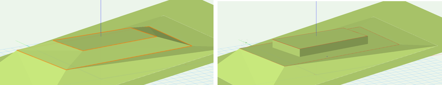
Vertical sides for inner modifiers |
Determines whether inner modifiers, such as a hardscape within grade limits, create a transitional surface (when disabled) or a vertical retaining edge (when enabled)
Vertical sides for inner modifiers deselected (on the left) and selected (on the right) |
|
Pad (Planar Pad configuration) |
|
|
Elevation |
Sets the elevation of the hardscape |
|
Slope Definition |
Select the method of defining the slope, or select None for a flat pad. After selecting the method, specify the Slope, the Elevation at End of the slope, or the Contour Angle, and the other values are automatically calculated and displayed. |
|
Aligned (Aligned configuration) |
Uses the hardscape as a non-planar slab that automatically matches relative elevations along horizontally collinear edges of adjacent roadways, hardscapes, massing models, extrudes, 3D polygons, landscape areas, walls, and pad/pad with retaining edge site modifiers |
|
Realign |
Resets the surface alignment with surrounding geometry |
|
Selects the objects to align to, based on the layer location of the objects. This offers flexible control over the alignment. All Layers: Aligns the hardscape with geometry from any layer in the file Visible Layers only: Aligns the hardscape with modifiers from visible layers only; geometry on invisible layers does not affect the hardscape Same Layer as Modifier: Aligns the hardscape with geometry that exists only on the same layer Select Layers: Opens the Select Layers dialog box, to choose which layers with geometry can affect the hardscapt alignment. Click in the Use column to select a layer. To create a new design layer, click New Layer; specify the name for the new layer, and click OK. Custom Set of Layers: Opens the Select Layers dialog box, to select or to modify the selected layers. |
|
|
Interpolate surface |
Increases the level of detail of the surface created by the profiles and modifiers |
|
Smoothness Sampling |
Enter the sampling rate (0 – 100); higher values add vertices and increase the smoothness |
|
Falloff |
Enter the percentage (0 – 100). This value determines the effect of the surface's defining elements (profiles, stakes, grade objects and adjacent objects) on the interpolated surface. The bigger the value, the less the influence of the defining elements. When the Interpolation Type is Concave, falloff values control the curvature of the surface. Larger falloff values result in a straighter, less curved surface; lower falloff values create a varied curved surface with hills and valleys. When the Interpolation Type is Convex, larger falloff values "pull" more on the surface points. The surface points may move close to the minimum elevation. |
|
Interpolation Type |
Select Concave or Convex, depending on the surface, the falloff value, and the desired results. Concave uses multiquadratic radial function calculations, and usually produces the best results. The surface effects are more stable and minimize the curvature. Convex uses inverse multiquadratic radial function calculations, and is useful when a bigger falloff is desired. The gravitational effect of this option pulls the surface points down to the minimum elevation based on their distance from the defining elements (profiles, stakes, grade objects and adjacent objects). |
|
Elevation |
Specifies the modifier elevation (does not apply to the aligned edges) |
|
Profiles (Aligned configuration) |
Modifies the surface of the hardscape with profile lines; see Editing aligned hardscapes or modifiers with profile lines |
|
Profile |
Scrolls through the profiles, highlighting the selected one; click the center button to highlight the current profile |
|
Name |
Displays the name of the currently selected profile |
|
Profile Line Class |
Select <Hardscape Class> to place the profile in the same class as the hardscape; select a class, or create a new class, to control profile line appearance and visibility. |
|
Show profile lines |
Toggles the display of all profile line parameters (name, slope, elevation, and markers) |
|
Show profile names |
Toggles the display of all profile names |
|
Show slopes |
Toggles the display of all slope values |
|
Show vertex elevation |
Toggles the display of all vertex elevations |
|
Show profile line markers |
Toggles the display of all profile markers |
|
Add Profile |
Adds a profile line to the hardscape for modifying the surface |
|
Edit Profile |
Enters editing mode for the selected profile, for Editing aligned hardscapes or modifiers with profile lines |
|
Reverse Direction |
Reverses the direction of the profile line section |
|
Profile Line Marker Styles |
Opens the Set Marker Style dialog box, to select the profile marker type at each end of the profile line; markers can be the same (Match Beginning) or different (Differentiate) at each end of the section line |
|
Delete Profile |
Deletes the selected profile |
|
Surface Modifiers (Aligned configuration) |
Modifies the surface of the hardscape with stake and grade objects |
|
Show stake objects |
After modifying the hardscape with stake objects, displays the stake objects |
|
Show grade objects |
After modifying the hardscape with grade objects, displays the grade objects |
|
Edit Surface Modifiers |
Edits the surface modifiers; see Editing aligned hardscapes or modifiers with surface modifiers |
|
Longitudinal Profile (Path configuration) |
|
|
Edit Profile |
Enters editing mode for the selected profile, for Editing aligned hardscapes or modifiers with profile lines |
|
Start Elevation/End Elevation |
Enter the starting and ending elevation of the modifier; alternatively, enter one of the elevations and ender a Slope value to automatically calculate the other elevation |
|
Slope |
Enter the slope value; alternatively, when the Start Elevation and End Elevation are entered, the slope displays |
|
Realign Elevations |
If changes occurred to an elevation, resets the affected vertex elevations |
|
Fit to Surface |
Conforms the longitudinal profile line to the surface of the site model |
|
Profile Line Class Profile Text Class |
Select <Hardscape Class> to place the profile or its label text in the same class as the hardscape; select a class, or create a new class, to control profile line appearance and visibility. |
|
Elevation Marker |
Select the elevation indicator type |
|
Elevation Marker Factor |
Specifies the scale factor of the elevation marker |
|
Slopes Grade Def |
Determines the how the Slope is calculated and displayed |
|
Show profile line |
Shows profile lines when profiles are added to edit the aligned slab (see Editing aligned hardscapes or modifiers with profile lines) |
|
Show slopes |
Toggles the display of all slope values |
|
Arrow indicates downward |
When Show slopes is selected, adds an arrow to indicate which side slopes down |
|
Show vertex elevation |
Toggles the display of all vertex elevations |
|
Show profile line markers |
Toggles the display of markers at the ends of the profile line |
|
Profile Line Marker Styles |
Opens the Set Marker Styles dialog box, to select the profile marker type at each end of the profile line; markers can be the same (Match Beginning) or different (Differentiate) at each end of the section line |
|
Transverse Profiles |
|
|
Profile |
Scrolls through the profiles, highlighting the selected one; click the center button to highlight the current profile |
|
Name |
Displays the name of the currently selected profile |
|
Profile Line Class Profile Text Class |
Select <Hardscape Class> to place the profile in the same class as the hardscape; select a class, or create a new class, to control profile line appearance and visibility |
|
Slopes Grade Def |
Determines the how the Slope is calculated and displayed |
|
Show profile lines |
Toggles the display of all profile line parameters (name, slope, elevation, and markers) |
|
Show profile names |
Toggles the display of all profile names |
|
Show slopes |
Toggles the display of all slope values |
|
Arrow indicates downward |
When Show slopes is selected, adds an arrow to indicate which side slopes down |
|
Show vertex elevation |
Toggles the display of all vertex elevations |
|
Show profile line markers |
Toggles the display of markers at the ends of the profile line |
|
Add Profile |
Adds a profile line for modifying the surface |
|
Edit Profile |
Enters editing mode for the selected profile, for Editing aligned hardscapes or modifiers with profile lines |
|
Profile Line Marker Styles |
Opens the Set Marker Style dialog box, to select the profile marker type at each end of the profile line; markers can be the same (Match Beginning) or different (Differentiate) at each end of the section line |
|
Delete Profile |
Deletes the selected profile |
|
Texture Bed (Texture Bed configuration) |
|
|
Texture from Class |
Select <Hardscape Class> to use the texture specified for the hardscape class; select a class, or create a new class, to control texture bed appearance and visibility. The indicated class should have a texture applied on the Textures pane, with Use at Creation selected. See Concept: Applying textures by class. |
|
Information |
|
|
Main Area |
Displays the size of the main area |
|
Border Area |
Displays the size of the border area |
|
Footprint Area |
Displays the area of the entire footprint of the hardscape |
|
Main Perimeter |
Displays the perimeter measurement of the main area polyline |
|
Border Perimeter |
Displays the perimeter of the border only |
|
Footprint Perimeter |
Displays the perimeter measurement of the entire footprint polyline |
|
Site Modifier Information |
|
|
Update Calculations |
Updates the area and volume calculations displayed in the Object Info palette for the area of the site model located under the hardscape modifier (grade limits must exist around the pad) |
|
Site model area and volume data |
Displays the area and volume information for the site model area located under the site modifier; select the units for the area and volume (grade limits must exist around the pad). For more information, see Site model properties. |
|
Vertex parameters |
Edits the vertices of the path object that the hardscape is based upon; see Editing vertex-based objects |
|
Render Tab |
|
|
Texture |
You can apply and manage textures for Slab and Slab Drainage type hardscapes on the Object Info palette Render tab. See Managing object textures from the Object Info palette and Textures on objects with components. |
To set individual border segments to invisible for boundary hardscapes or cut-out holes, select the hardscape object, and then click the Reshape tool. Click Hide or Show Edges mode. Click the midpoint of the hardscape border segments or the cut-out hole to hide. Repeat this process to set the border segments back to visible, if necessary.
To quickly determine the left and right side of a pathway hardscape object, select the hardscape object and click the middle button next to the Vertex field on the Shape tab of the Object Info palette; when the button is clicked, the first vertex of the hardscape object is highlighted with a red box.
When classing the subcomponents of the hardscape object, such as for the joints or tags, the class visibility of the specified class controls the visibility of the corresponding subcomponent. The class attributes are only applied to the corresponding subcomponent when the Use at Creation option is selected for the class. For example, if the Joint Class is set to the Hardscape - Component - Main Joint class, and that class specifies a hatch Fill Style, edit the class and select the Use at Creation option to apply the fill attribute. See Setting class attributes.
A hardscape object can be used as the basis of a retaining wall. This provides the ability to sculpt the site model around the hardscape. See Creating retaining walls.
