 Creating hardscapes
|
Tool |
Tool set |
|
Hardscape
|
Site Planning |

A hardscape object consists of paved areas with joint patterns and optional borders. Multiple types and configurations of hardscape can be created, and they can be used either to modify the site model, conform to the site model or simply produce a texture overlay on the site model surface. See Concept: Hardscape types if you aren't sure what type of hardscape object to create based on your design needs.
For styled objects, only parameters set by instance can be edited from the Hardscape Preferences dialog box and Hardscape Object Settings dialog box. For more information about using and creating styles, see Concept: Plug-in object styles.
To draw a hardscape object, either use the Hardscape tool, or create a closed 2D shape and then select the Create Objects from Shapes command (see Creating objects from shapes).

|
Mode |
Description |
|
Hardscape list |
Opens the Resource Selector to select a resource for placement; double-click a resource to activate it |
|
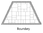
Boundary Configuration
|
Creates a hardscape with a boundary configuration, defining an area with an optional border |
|
Aligned Configuration
|
Creates a 3D slab type hardscape which aligns with surrounding geometry |
|
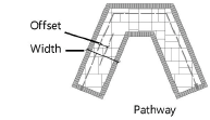
Pathway Configuration
|
Creates a hardscape along a path |
|
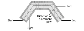
Pathway Edge options |
For the pathway configuration, sets where to create the pathway in relation to the drawn polyline |
|
Polyline creation options |
Selects the method for drawing the polyline upon which the hardscape object is based; see Polyline tool |
|
Preferences
|
Sets the default preferences for the hardscape object |

To create a hardscape object:
Click the tool and appropriate hardscape configuration mode; if using the Pathway Configuration mode, select the pathway edge option. The hardscape configuration can also be changed after creation from either the Hardscape Object Settings dialog box or the hardscape context menu commands (see Converting a hardscape object to different configuration).
Do one of the following:
Click Hardscape on the Tool bar to select a resource from the Resource Selector.
Click Preferences to open the Hardscape Preferences dialog box and specify the tool’s default parameters.
The parameters (along with additional parameters) can be edited later from the Object Info palette; see Hardscape properties.
Click to show/hide the parameters.Click to show/hide the parameters.
|
Parameter |
Description |
|
Hardscape Style |
Opens the Resource Selector to select a resource for placement. If accessing the hardscape settings from the Edit Hardscape Style dialog box, a Load Settings (legacy) option is available to load the parameter settings for a hardscape object from Vectorworks versions prior to version 2022. |
|
Convert to Unstyled |
If Use Style is currently set to a style, select this option to convert the object to unstyled; the current values are retained, but all parameters are set to By Instance to allow editing |
|
Configuration |
When Preferences is accessed from the Tool bar, the selected Configuration automatically switches the selected mode on the Tool bar to match when the Preferences dialog box closes |
|
Boundary |
Defines the hardscape object with a user-defined polyline as the outer edge of the hardscape object (for example, to define regular or irregular patio areas).
|
|
Pathway |
Defines the hardscape object with a user-defined polyline as an alignment for a linear path
|
|
Width |
Width of the pathway hardscape object |
|
Offset |
Sets the offset of the pathway centerline from the placement line |
|
Main Unit Price/ Main Price Code/ Border Unit Price/ Border Price Code |
Enter the price per unit and the price code for the main hardscape, and optionally, the border, for reporting purposes |
|
Draw 2D |
|
|
Joint Pattern |
Select the main hardscape joint pattern; see Specifying hardscape joint patterns |
|
Pattern |
Displays the selected joint pattern name |
|
Joint Angle |
Sets the main hardscape joint angle |
|
Main Area Class |
To control appearance and visibility, select a class for the joint pattern from the list of classes present in the drawing, or create a new class |
|
Draw border |
Includes a border pattern along the edges of the hardscape object |
|
Width |
Enter the width of the border |
|
Joint Pattern |
Select the border joint pattern. For more information, see Specifying a hatch, stipple, or tile joint pattern and Specifying a spaced joint pattern. The selected pattern displays. |
|
Joint Angle |
Sets the border joint angle |
|
Background Color |
Click the color box to select the desired border color |
|
Border Class |
To control appearance and visibility, select a class for the border joint pattern from the list of classes present in the drawing, or create a new class |
|
Pathway Borders |
Select the border configuration for pathway hardscape objects with borders
|
|
Draw 3D |
|
|
3D Type |
Select the 3D hardscape format. See Creating hardscape objects for more information. None displays a schematic view of the hardscape in 3D views. Slab creates a slab type hardscape for the main hardscape and a border hardscape for the border, if one is specified. Slab Drainage creates a slab type hardscape for the main hardscape to support a drainage system; see Creating slab drainage systems. If a border is specified, a border hardscape is created, but drainage elements are not applied to it. When Slab Drainage is selected, the Slab Drainage tool can modify the main hardscape, adding slopes and ridges to the main slab geometry. You can apply and manage textures for Slab and Slab Drainage type hardscapes on the Object Info palette Render tab. See Managing object textures from the Object Info palette and Textures on objects with components. |
|
Configuration |
Indicates how the hardscape interacts with the site model. The selection made here changes the parameters available from the Object Info palette. No Site Modifier: the hardscape does not modify the site model. Planar Pad: A 3D polygon defines the shape of an element which is added to, and normally modifies, the site model. The site model is made planar beneath the hardscape, similar to a planar pad modifier; see Creating a planar pad or pad with retaining edge. Aligned: Defines a surface based on surrounding surfaces and modifiers, matching their elevation; see Creating an aligned site modifier. Path: Creates a surface defined by one longitudinal profile and a set of transverse profiles, with the path defined as a polyline; see Creating a pathway or boundary modifier. Texture Bed: Creates a texture bed out of the hardscape modifier, similar to the texture bed modifier; see Creating a texture bed. Draped: Conforms the hardscape to the site model surface rather than modifying it. |
|
Main Area Components |
Opens the Hardscape Main Area Components dialog box, to specify the components; see Creating hardscape components |
|
Border Components |
Opens the Hardscape Border Components dialog box, to specify the components for the hardscape border; see Creating hardscape components |
|
Main Area Thickness |
Displays the main area hardscape thickness. The hardcape thickness is always determined by the thickness of its components; a hardscape always has one component by default. |
|
Drainage Settings (Slab Drainage type) |
Opens the Slab Drainage Settings dialog box. These settings are identical to those of a slab; see Slab drainage settings. |
|
Tag |
In addition to these options, you may wish to investigate the flexibility offered by the Data Tag tool; see Adding data tags and labels |
|
Tag Display |
Select whether to display the hardscape tag to the right or left of the leader line, without a leader line (floating), or not at all |
|
Tag Style |
Select the ID tag display style. Name Only displays the name of the hardscape object only (as defined in the Name field). Name-Area(s) displays the hardscape object name, main area, and area of the border if applicable. Name-Area(s)-Perim displays the hardscape object name, main area, area of the border if applicable, and perimeter length. |
|
Tag Class |
To control appearance and visibility, select a class from the list of classes present in the drawing, or create a new class. Select <Hardscape Class> to place the tag in the same class as the hardscape object. |
|
Tag Approach Angle |
Specifies the angle of the leader line, from 0 to 360°. Setting the same angle for several selected hardscapes aligns their leader lines, for an attractive plan (see Aligning and distributing leader lines). |
|
Tag Shoulder Angle |
When a tag shoulder line is enabled, sets the angle of the shoulder line and, if selected, tag display, from 0 to 360°. To display the tag to the left, specify an angle greater than 90 or less than 270 degrees. To display the tag to the right, specify an angle less than 90 or greater than 270 degrees. Setting the same angle for several selected hardscapes aligns their shoulder lines, for an attractive plan. |
|
Tag Text Alignment |
Select whether the tag text is aligned on top of a continuation of the leader line, or centered vertically at the end of the leader line |
|
Snap tag to hardscape edge |
Select this option to automatically align the endpoint of the tag with the edge or corner of the hardscape that is nearest to the shoulder point of the tag |
|
Display tag line marker |
Displays a marker at the end of the leader line; specify the marker style by editing the hardscape tag class (see Setting class properties) |
The Stipple joint patterns are processor-intensive for large hardscape objects and can significantly increase regeneration time.
When drawing a hardscape object with a curved boundary, speed the regeneration time by setting the 2D Conversion Resolution in Vectorworks preferences to low (see Vectorworks preferences: Edit pane).
Select the polyline creation mode; see Polyline tool.
Click to set the hardscape object’s start point.
Click to set the end of the segment and the beginning of the next. Continue drawing segments in this manner until the hardscape object is complete. Return to the start point (for boundary and aligned configurations), or simply double-click to finish creating the hardscape object.
For aligned configuration hardscapes, ensure that Snap to Object is selected in the Snapping set on the Status bar. Draw the hardscape by tracing along the edges of valid objects that the hardscape should align to; valid alignment objects are highlighted as you draw. The hardscape’s edge aligns with the adjacent object according to the top or bottom of the hardscape’s specified Datum component. The datum is determined either by the hardscape style or set from the Object Info palette by clicking Main Area Components (or Border Components) to open the hardscape Components dialog box; see Creating hardscape components.
See Aligning hardscapes or modifiers with existing geometry for more information on aligned surface slabs.
When classing the subcomponents of the hardscape object, such as the joints or tags, the class visibility of the specified class controls the visibility of the corresponding subcomponent. The class attributes are only applied to the corresponding subcomponent when the Use at Creation option is selected for the class. For example, if the Joint Class is set to the Site-Hardscape Comp-Main Joint class, and that class specifies a hatch Fill Style, edit the class and select the Use at Creation option to apply the fill attribute.
If the hardscape is a site modifier, update the site model to apply the modification. Click Update Site Model from the Object Info palette.
Optionally, create a style resource from an unstyled object (see Custom plug-in object styles without catalog options).
